|
|
||
|---|---|---|
| .. | ||
| doc/images | ||
| src/main | ||
| NOTICE | ||
| pom.xml | ||
| README.md | ||
TA C.M.I. Binding
This binding makes use of the CAN over Ethernet feature of the C.M.I. from Technische Alternative. Since I only have the new UVR16x2, it has only been tested with this controller.
The binding supports two ways to interact with the C.M.I. and all devices connected to the C.M.I. via the CAN bus. These modes are:
Via a "Schema API Page"
- Read values from output nodes
- Change values for controllable nodes
CoE (CAN over Ethernet) Connection
- Receive data from analog CAN-outputs defined in TAPPS2
- Receive data from digital CAN-outputs defined in TAPPS2
- Send ON/OFF to digital CAN-inputs defined in TAPPS2
- Send numeric values to analog CAN-inputs defined in TAPPS2
Depending on what you want to achieve, either the "Schema API Page" or the CoE way might be better. As rough guidance: Anything you want to provide to the TA equipment it has to work / operate with the CoE might be better. If you plan things mainly for user interaction the "Schema API Page" might be better.
Prerequisites
Setting up the "Schema API Page"
The "Schema API page" is a special schema page created via TA's TA-Designer application available as download on their web site. This page just needs to exist and be deployed on the C.M.I. but it dosn't need to be linked by the other schema pages you are using to control your TA installation.
All objects from this special 'API' page are automatically mapped as channels of this thing, so the labels of the objects on this page have to follow a specific schema.
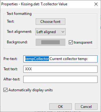
When adding objects to this page, the schema for the Object's Pre-Text field has to follow the schema <channelName> <channel description>:.
Maybe this screenshot shows it best:
The Text from the Pre-Text will be used to define the channel. The first word tempCollector (highlighted in the screenshot) will be used as channel name, so it has to be unique. Everything else till the final : will be used as channel description. Be sure to have at least 2 words in the Pre-Text as we need both - the channel name and a description. The binding will log an error otherwise. Also keep in mind: for the channel name we have to adhere to the openHAB channel name conventions - so just use letters and numbers without any special sings here. The type of the channel will be automatically determined by the type of the object added. Also don't forget the final colon - this is the separator between the label and the value. Without the colon the parser couldn't build up a working channel for this value.
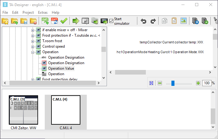
The first sample is a sensor reading, but also the 'operation mode' of a heating circuit could be added:
In this screenshot you also see the schema page id - the parenthesized number on the bottom page overview, in this sample 4.
CoE Configuration
Configure CAN outputs in TAPPS2
You need to configure CAN outputs in your Functional data on the UVR16x2. This can be done by using the TAPPS2 application from TA. Follow the user guide on how to do this.
Configure your CMI for CoE
Now follow the User Guide of the CMI on how to setup CAN over Ethernet (COE). Here you will map your outputs that you configured in the previous step. This can be accomplished via the GUI on the CMI or via the coe.csv file. As the target device you need to put the IP of your openHAB server. Don’t forget to reboot the CMI after you uploaded the coe.csv file.
Supported Bridge and Things
- TA C.M.I. schema API connection - Thing
This thing reflecting one of our 'schema API page' as defined in the prerequisites. This thing doesn't need the bridge. Multiple of these pages on different C.M.I.'s could be defined within an openHAB instance.
- TA C.M.I. CoE Bridge
In order to get the CAN over Ethernet (COE) envionment working a coe-bridge has to be created.
The bridge itself opens the UDP port 5441 for communication with the C.M.I. devices.
The bridge could be used for multiple C.M.I. devices.
- TA C.M.I. CoE Connection - Thing
This thing reflects a connection to a node behind a specific C.M.I.. This node could be every CAN-Capable device from TA which allows to define a CAN-Input.
Discovery
Autodiscovering is not supported. We have to define the things manually.
Thing Configuration
TA C.M.I. schema API connection
The TA C.M.I. Schema API Connection has to be manually configured.
The thing has the following configuration parameters:
| Parameter Label | Parameter ID | Description | Accepted values |
|---|---|---|---|
| C.M.I. IP Address | host | Host name or IP address of the C.M.I | host name or ip |
| Username | username | Username for authentication on the C.M.I. | string with username |
| Password | password | Password for authentication on the C.M.I. | string with password |
| API Schema ID | schemaId | ID of the schema API page | 1-256 |
| Poll Interval | pollInterval | Poll interval (in seconds) how often to poll the API Page | 1-300; default 10 |
This thing doesn't need a bridge. Multiple of these things for different C.M.I.'s could be defined within an openHAB instance.
TA C.M.I. CoE Connection
The TA C.M.I. CoE Connection has to be manually configured.
This thing reflects a connection to a node behind a specific C.M.I.. This node could be every CAN-Capable device from TA which allows to define a CAN-Input.
| Parameter Label | Parameter ID | Description | Accepted values |
|---|---|---|---|
| C.M.I. IP Address | host | Host name or IP address of the C.M.I | host name or ip |
| Node | node | The CoE / CAN Node number openHAB should represent | 1-64 |
The thing has no channels by default - they have to be added manually matching the configured inputs / outputs for the related CAN Node. Digital and Analog channels are supported. Please read TA's documentation related to the CAN-protocol - multiple analog (4) and digital (16) channels are combined so please be aware of this design limitation.
Channels
TA C.M.I. schema API connection
The channels provided by this thing depend on the configuration of the "schema API page". All the channels are dynamically created to match it. Also when the API Page is updated, the channels are also updated during the next refresh.
The channels have a parameter allowing to configure their update behavior:
| Parameter Label | Parameter ID | Description | Accepted values |
|---|---|---|---|
| Update Policy | updatePolicy | Update policy for this channel. Default means "On-Change" for channels that can be modified and "On-Change" for read-only channels. | 0 (Default), 1 (On-Fetch), 2 (On-Change) |
The behavior in detail:
Default(0): When the channel is 'read-only' the update-policy defaults to On-Fetch . When the channel is linked to something that can be modified it defaults to On-Change .On-Fetch(1): This is the default for read-only values. This means the channel is updated every time the schema page is polled. Ideally for values you want to monitor and log into charts.On-Change(2): When channel values can be changed via OH it is better to only update the channel when the value changes. The binding will cache the previous value and only send an update when it changes to the previous known value. This is especially useful if you intend to link other things (like i.e. Zigbee or Shelly switches) to the TA via OH that can be controlled by different sources. This prevents unintended toggles or even toggle-loops.
TA C.M.I. CoE Connection
Some comments on the CoE Connection and channel configuration: As you might already have taken notice when studying the TA's manual, there are always a multiple CoE-values updated within a single CoE-message. This is a design decision made by TA. But this also means for CoE-Messages from openHAB to TA C.M.I. we have to send multiple values at once. But due to OH's design there is no default restore of previous values out of the box. So after OH startup the output thing channels are either initialized with it's configured default value or flagged as 'unknown' until the first update on the channel happens. You could either use some 'illegal' value as initial value and use CoE Value Validation on the TA side to detect invalid values. Another option would be to use only every 4th analog and 16th digital channel if you only need a few channels. Additionally you could use OH's persistence service and it's option to restore the item states during OH startup. As this only restores the item states you have to write a rule issuing postUpdates on the items with the item's current value so the channel for the binding is updated.
Supported channels for the CoE connection are:
| Channel | Type | Description |
|---|---|---|
| coe-digital-in | Switch (RO) | Digital input channel for digital state data received from the node |
| coe-digital-out | Switch | Digital output channel for digital state data sent to the node |
| coe-analog-in | Number (RO) | Analog input channel for numeric values received from the node |
| coe-analog-out | Number | Analog output channel for numeric values sent to the node |
Each channel has it's own set of configuration parameters. Here a list of possible parameters:
Channel's coe-digital-in and coe-analog-in:
| Parameter Label | Parameter ID | Description | Accepted values |
|---|---|---|---|
| Output | output | C.M.I. Network Output | 1-64 |
Channel coe-digital-out:
| Parameter Label | Parameter ID | Description | Accepted values |
|---|---|---|---|
| Output | output | C.M.I. Network Output | 1-64 |
| Initial Value | initialValue | Initial value to set after startup (optional, defaults to uninitialized) | true (on) / false (off) |
Channel coe-analog-out:
| Parameter Label | Parameter ID | Description | Accepted values |
|---|---|---|---|
| Output | output | C.M.I. Network Output | 1-64 |
| Measurement Type | type | Measurement type for this channel (see table below) | 0-21 |
| Initial Value | initialValue | Initial value to set after startup (optional, defaults to uninitialized) | floating point numeric |
The binding supports all 21 measure types that exist according to the TA documentation. Unfortunately, the documentation is not consistent here, so most of the types are supported only by generic names. The known measure types are:
| id | type | description |
|---|---|---|
| 1 | Temperature | Tempeature value. Value is multiplied by 0.1 |
| 2 | Unknown2 | |
| 3 | Unknown3 | |
| 4 | Seconds | |
| 5...9 | Unknown5..9 | |
| 10 | Kilowatt | |
| 11 | Kilowatthours | |
| 12 | Megawatthours | |
| 13..21 | Unknown |
Full Example
As there is no common configuration as everything depends on the configuration of the TA devices. So we just can provide some samples providing the basics so you can build the configuration matching your system.
Example of a .thing file:
Thing tacmi:cmiSchema:apiLab "CMIApiPage"@"lab" [ host="192.168.178.33", username="user", password="secret", schemaId=4 ]
Bridge tacmi:coe-bridge:coe-bridge "TA C.M.I. Bridge"
{

    Thing cmi cmiTest "Test-CMI"@"lab" [ host="192.168.178.33", node=54 ] {
    Channels:
        Type coe-digital-in : digitalInput1 "Digital input 1" [ output=1 ]
        Type coe-digital-out : digitalOutput1 "Digital output 1" [ output=1, initialValue=true]
        Type coe-analog-in : analogInput1 "Analog input 1" [ output=1 ]
        Type coe-analog-out : analogOutput1 "Analog output 1" [ output=1, type=1, initialValue=22 ]
    }

}
Sample .items-File:
# APIPage-items
Number TACMI_Api_tempCollector "Collector temp [%.1f °C]" <temperature> {channel="tacmi:cmiSchema:apiLab:tempCollector"}
String TACMI_Api_hc1OperationMode "Heating Curcuit 1 Operation Mode [%s]" {channel="tacmi:cmiSchema:apiLab:hc1OperationMode"}


# COE-items
Number TACMI_Analog_In_1     "TA input value 1 [%.1f]"  <temperature> {channel="tacmi:cmi:coe-bridge:cmiTest:analogInput1"}
Number TACMI_Analog_Out_1    "TA output value 1 [%.1f]" <temperature> {channel="tacmi:cmi:coe-bridge:cmiTest:analogOutput1"}
Switch TACMI_Digital_In_1    "TA input switch 1 [%s]"    {channel="tacmi:cmi:coe-bridge:cmiTest:digitalInput1"}
Switch TACMI_Digital_Out_1   "TA output switch 1 [%s]"   {channel="tacmi:cmi:coe-bridge:cmiTest:digitalOutput1"}
Sample .sitemap snipplet
sitemap heatingTA label="heatingTA"
{
    Text item=TACMI_Api_tempCollector
    Switch item=TACMI_Api_hc1OperationMode mappings=["Zeit/Auto"="Auto", "Normal"="Operating", "Abgesenkt"="lowered", "Standby/Frostschutz"="Standby"]

    Text item=TACMI_Analog_In_1
    Setpoint item=TACMI_Analog_Out_1 step=5 minValue=15 maxValue=45
    Switch item=TACMI_Digital_In_1
    Switch item=TACMI_Digital_Out_1
}
Some additional hints and comments
Some additional hints and comments:
You might already have noticed that some state information is in German.
As I have set the Accept-Language-Http-Header to en for all request and found no other way setting a language for the schema pages I assume it is a lack of internationalization in the C.M.I.
You could circumvent this by creating map files to map things properly to your language.
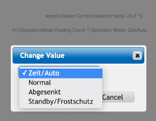
If you want to see the possible options of a multi-state field you could open the schema API page with your web browser and click on the object. A Popup with an option field will be shown showing all possible options, like in this screenshot:
Please be also aware that there are field having more 'state' values than options, i.E. a manual output override: It has 'Auto/On', 'Auto/Off', 'Manual/On', 'Manual/Off' as state, but only 'Auto', 'Manual/On' and 'Manual/Off' as updateable option. You only set it to 'Auto' and the extension On/Off is added depending on the system's current state.


